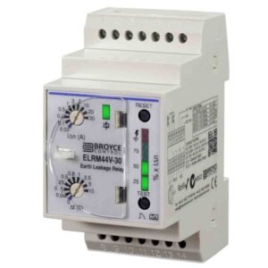
Unexpected shutdowns are frustrating, particularly when a machine restarts normally and the fault seems to disappear. An SPNO Earth Leakage Relay can reveal changing residual current, but a trip is a warning to investigate, not an inconvenience to bypass. Understanding the pattern behind repeated operation helps maintenance teams protect people and equipment while avoiding unnecessary component replacement.
A practical SPNO Earth Leakage Relay works with an appropriate residual-current sensor and an external control or disconnection arrangement. Its normally-open output can take part in a trip or alarm circuit, depending on the design. However, the relay itself does not interrupt power conductors, so the complete protective function must be checked before anyone relies on it.
Why Can Earth Leakage Trips Be Intermittent?
Electrical insulation rarely deteriorates on a convenient schedule. A damp junction box might produce higher leakage after cleaning, while a cable could move against a sharp edge only when machinery vibrates. Some installations also have normal background leakage from filters and connected equipment. Changes in that combined current may bring the measured value closer to the configured threshold.
Consequently, repeated trips do not prove a defective relay. The monitored circuit, environmental conditions, sensor installation and output wiring all need consideration. Treat every event as potentially genuine until competent testing establishes otherwise.
What Clues Should You Record First?
Before changing anything, note the time, affected equipment and conditions at each event. A clear event history often narrows the investigation faster than repeatedly resetting the device.
- Did the trip follow rainfall, washdown or condensation?
- Did it occur when a motor, heater or drive started?
- Does it affect one operating mode or several?
- Was any wiring or equipment recently added?
- Was a sensor fault or loss-of-supply indication displayed?
Preserve available logs and indicator readings, including those from Panel Meters where fitted. Do not assume an indicator proves which individual component caused the leakage.
How Can a Maintenance Team Separate Cause From Symptom?
Start with the installation drawings and the relay manufacturer’s instructions. Identify what each monitored sensor encloses, which output operates the external switch, and how the system responds to a loss of auxiliary supply. Documented wiring matters because different output arrangements can behave differently during faults.
Qualified personnel should isolate hazardous energy and verify isolation before opening panels or disconnecting conductors. Visual inspections may identify damaged insulation, wet enclosures or loose terminations. Cable Markers can help match the affected conductors with the correct schematic during controlled fault finding.
Could Moisture Be Responsible?
Yes. Water ingress, conductive dust and contaminated terminal surfaces can create unintended leakage paths. However, a dry-looking enclosure is not proof of sound insulation. Moisture can remain inside cable glands or equipment long after the exterior appears normal.
Inspect Cable Glands and DIN Rail Enclosures against their intended protection ratings. Replace damaged parts using approved procedures instead of relying on temporary drying or repeatedly clearing the alarm.
Which Tests Help Identify Insulation Problems?
After safe isolation and any required disconnection of sensitive electronics, appropriately selected Insulation Testers can help competent technicians evaluate insulation resistance. Test voltage, circuit preparation and acceptance limits must follow the relevant equipment instructions and installation standards.
An insulation test is not a universal live-leakage measurement. It may expose deteriorating insulation, but normal operating conditions, connected filters and electronic drives can require a different diagnostic approach. Record readings against appropriate baselines rather than guessing from a single number.
Why Must the Sensor Arrangement Be Checked?
In a typical core-balance arrangement, all relevant live conductors, including neutral where applicable, pass through the sensing aperture. A protective-earth conductor must not be routed through it as though it were a return conductor. Incorrect routing can create misleading measurements or defeat the intended detection principle.
Check sensor compatibility, cable placement and the continuity of its connection to the relay using the manufacturer’s instructions. Never unplug a live sensor circuit merely to see whether a trip stops.
Can Normal Equipment Leakage Trigger a Warning?
Some electronic equipment produces small residual currents during normal operation, particularly when electromagnetic-interference filters are present. Several loads on one monitored circuit can contribute to a combined reading. That does not justify simply raising the trip setting.
A competent designer must assess the intended protection, permissible leakage, time discrimination and applicable standards. Settings selected to prevent nuisance operation could leave a dangerous fault undetected or delay required disconnection.
How Should You Measure Leakage Under Operating Conditions?
A suitably rated leakage-current instrument, including specialist Clamp Meters, may help trained personnel investigate residual current under controlled conditions. Not every ordinary clamp meter has the sensitivity or measurement mode needed for this task.
Live measurements introduce hazards and require an approved method, correct instrument ratings and competent operators. When results suggest abnormal behaviour, investigate the affected equipment rather than altering protection settings to hide it.
What Should a Reset and Functional Test Prove?
A reset should follow a documented assessment of the fault. Depending on the device, a front-panel test may confirm part of the relay’s logic without proving that the external contactor, breaker mechanism or wiring actually disconnects the intended circuit.
Commissioning and periodic verification should cover the full chain, from sensor and settings through to indications and the final switching device. Document the expected response to a genuine fault, sensor disconnection and loss of supply as appropriate to the design.
How Can You Reduce Repeat Trips Without Reducing Protection?
Combine accurate event records, sound cable routing, suitable environmental sealing and scheduled inspection. Review changes to connected equipment before treating a trip as random. An organised maintenance process also makes it easier to distinguish normal leakage trends from sudden deterioration.
For wider electrical-system monitoring, compare suitable Monitoring Relays according to the fault being detected, output behaviour and required integration. The goal is not to silence a warning, but to identify its cause and keep the designed protection dependable.