A machine can be mechanically sound yet produce uneven cuts or unexpected speed readings. Sometimes the problem is not the motor or controller but the quality of the motion feedback reaching the control system. Incremental encoders create electrical pulses that represent movement, and reliable operation depends on counting those pulses accurately. Understanding disruptions helps technicians diagnose faults.
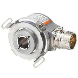
A Kübler Incremental Encoder is one example of a sensor used to monitor rotating shafts in automated equipment. Instead of focusing on a single model, this guide examines the entire feedback path: shaft movement, signal generation, cables and controller interpretation. Troubleshooting begins by identifying where information is lost.
How Does an Incremental Encoder Translate Rotation Into Data?
An incremental encoder generates a sequence of pulses as its shaft rotates. The controller counts transitions to estimate movement and measures pulse frequency to calculate speed. Many encoders provide two channels, A and B, with a phase difference. By comparing their timing, suitable electronics can infer the direction of rotation.
Some models also provide a reference, or index, pulse once per revolution. That signal can help a machine establish a repeatable reference, but it does not automatically reveal absolute position when power returns. A reference or homing procedure may still be required.
Why Do Pulses Per Revolution Matter?
Pulses per revolution, often abbreviated PPR, describe the encoder’s nominal pulse output for one mechanical turn. Higher PPR can improve measurement granularity, but increases the number of transitions the controller must process.
Quadrature decoding adds another consideration. A controller using four-edge counting may register four counts per pulse cycle, so its reported counts per revolution differ from the PPR printed on the encoder. Incorrect scaling can make a functioning machine appear to move too quickly, too slowly or by the wrong distance.
How Does Operating Speed Affect Pulse Counting?
An encoder that works at low speed can appear unreliable when the machine accelerates. The expected channel frequency rises with shaft speed and pulse resolution. For example, a 1,000 PPR encoder rotating at 3,000 rpm produces 50,000 pulse cycles per second on each principal channel, before considering quadrature edge multiplication.
If the receiving hardware cannot handle the resulting transitions, it may miss counts. Check the encoder’s output frequency rating and the counter’s supported input rate rather than assuming that greater resolution always improves practical accuracy.
What Causes Lost or Unstable Encoder Signals?
A reading that occasionally jumps or freezes does not always mean the sensor has failed. Signal problems can develop elsewhere in the installation.
Which Faults Should Technicians Investigate?
- Electrical noise: Motor drives and switching equipment may introduce interference into inadequately protected signal cables.
- Loose connections: Intermittent terminals can create missing edges or unexpected transitions.
- Input limitations: A controller may be unable to count pulses at the highest operating speed.
- Incorrect configuration: Wrong edge-counting settings or scaling values can distort readings.
- Mechanical slipping: Poor shaft attachment can make encoder rotation differ from machine movement.
The symptoms provide clues. Speed-related errors may indicate an input-frequency limit, while faults near a variable-speed drive may suggest interference. Testing should distinguish these possibilities before any parts are changed.
How Can Wiring Improve Motion Feedback Reliability?
Encoder wiring must match the output stage and receiving input. Push-pull, open-collector and differential line-driver signals are not interchangeable without compatible electronics. Supply voltage, conductor assignment, grounding and any required termination must follow the manufacturer’s documentation.
Appropriate Sensor & Switch Cables & Connectors help technicians plan reliable connections for industrial sensing equipment. Where recommended, use screened cables, suitable separation from power wiring and proper shield termination. Avoid assuming that grounding both ends or adding resistance is always correct; the system design determines the appropriate arrangement.
How Do You Check the Controller’s Pulse Count?
Begin by making the machinery safe, then inspect the documented wiring and settings. With authorised testing arrangements, rotate the shaft through a known movement and compare the expected count with the controller reading. Check whether direction reversals produce the intended sign and whether the index pulse appears where configured.
A suitable oscilloscope or counter can help verify pulse quality and timing, but its input range and connections must match the circuit. Never probe hazardous equipment without the appropriate competence and isolation procedures.
Can Mechanical Installation Create Measurement Errors?
Yes. An encoder mounted off-axis may experience unnecessary bearing loads, while a loose coupling can introduce backlash or slip. Those faults can resemble electrical problems because the detected shaft position no longer represents the intended machine movement.
For solid-shaft arrangements, correctly sized Flexible Couplings can accommodate limited shaft misalignment where the manufacturer permits their use. They cannot correct severe alignment errors. Hollow-shaft designs have different mounting requirements, including appropriate torque supports or restraints.
How Can Preventive Checks Reduce Repeat Faults?
Record the actual symptoms, operating speed, ambient conditions and any recent equipment modifications. Inspect cable routing, connectors, coupling condition and ingress protection during planned maintenance. If pulses disappear only under load, investigate vibration and interference together instead of treating them as separate issues.
A well-matched feedback system combines correct hardware with consistent software scaling and documented maintenance checks. Where a machine has been modified, retest at both low and normal operating speeds so faults do not remain hidden until production resumes.
Why Is Reliable Encoder Feedback Important for Automation?
Reliable pulse feedback helps equipment maintain predictable speed, distance and direction calculations. Better measurements can reduce scrap, simplify diagnosis and prevent unnecessary component replacement. The most effective approach considers the full signal chain rather than blaming the encoder whenever a reading changes. When connecting sensors to PLCs (Programmable Logic Controllers), make sure the selected controller or high-speed counter can process the expected pulse frequency and decoding method. Correct mounting, appropriate wiring, verified input settings, and systematic testing make motion feedback more dependable as machinery evolves.